Inter-Integrated Circuit (I2C) is a serial communication protocol used to connect microcontrollers and other digital circuits to peripheral devices such as sensors, memory, and other components. It was developed by Philips (now NXP Semiconductors) in the early 1980s and has since become a widely adopted standard in the electronics industry.
In this blog, we will explore the basics of the I2C protocol, its features, and its usage in different applications.
Introduction
I²C, which stands for Inter-Integrated Circuit, is indeed a data bus used for communication between various devices. It facilitates the interaction between microcontrollers (µC) and components such as displays and sensors. One notable feature of I²C is its ability to communicate with up to 128 participants using just two lines. This bus utilizes serial data transmission, where information is transmitted sequentially through a single line, and the I²C protocol defines the specific procedure for accomplishing this communication.
| Transfer rate | Rate | Data transmission | Direction |
| 0.1 Mbit/s (standard) | Synchronous | Serial | Bidirectional |
Construction:
The I²C consists of several participants. who can communicate togetherÖ
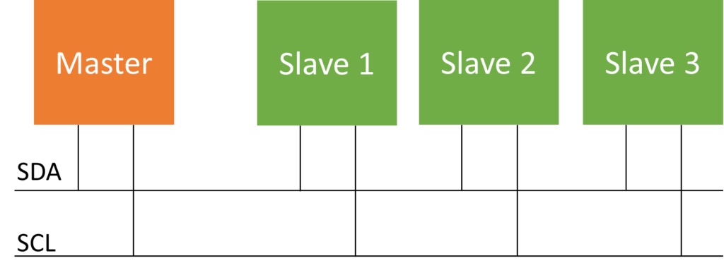
There are two distinct types of participants in a system: masters and slaves. This differentiation is commonly used when referring to microcontroller (µC) systems, where the µC acts as the master and various peripherals such as sensors and displays act as slaves.
Typically, there is a single master in a system, although in certain cases, multiple masters can be supported, resulting in a “multi-master bus.” However, it is important to note that there should not be more than 127 slaves in the system.
The communication between the master and slaves occurs over a bus consisting of two lines. One of these lines is called SDA (Serial Data), and data is transmitted serially over this line, hence its name. Both the master and slaves can send and receive data on this line.
The second line is SCL (Serial Clock), which is responsible for transmitting clock pulses. The clock pulses synchronize the data transmission between the master and slaves. Since all participants on the bus utilize a common clock, this type of bus is referred to as a synchronous bus.
Sequence
Data transmission on the I2C bus occurs in a serial manner, where each piece of data is sent sequentially. This necessitates the use of a protocol that defines the specific order in which data is transmitted. The protocol serves as a guide or set of rules that ensure proper organization and enables all participants to understand what data is being sent and when.
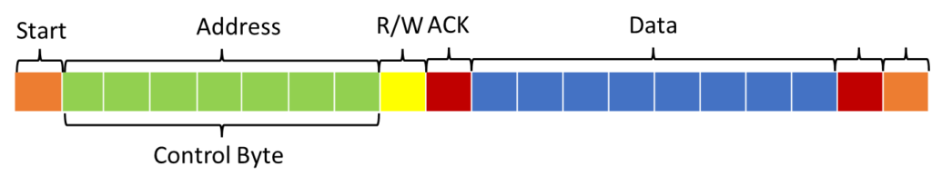
Below is the outline of the I2C protocol, which will be further explained:
- Start condition: The master initiates communication by sending a start condition, signaling the beginning of a transaction.
- Address byte: The master sends the address byte, which identifies the specific slave device it wants to communicate with.
- Read/write bit: The master sends a read/write bit along with the address byte to indicate whether it intends to read data from or write data to the slave device.
- Acknowledgment: After each byte is sent, the sender expects an acknowledgment from the receiver. This acknowledgment confirms that the data was successfully received.
- Data transmission: The master and slave devices take turns transmitting data. The master sends the data byte, and the slave responds with an acknowledgment. This process continues until all the required data has been transferred.
- Acknowledgment: As soon as all data has been sent, the acknowledgment comes.
- Stop condition: The master sends a stop condition to indicate the end of the transaction.
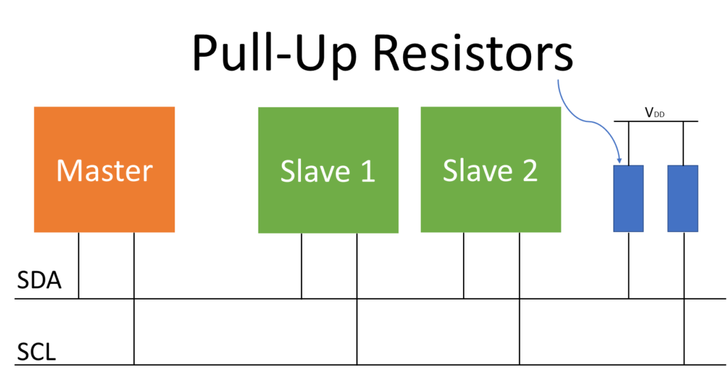
Pull up resistors
One notable characteristic of the I2C bus is that when no communication is taking place, both bus lines, SDA and SCL, are in a high state, typically at a voltage level of 5V. This behavior is achieved by incorporating pull-up resistors on both lines. The pull-up resistors ensure that the lines remain in a high state when not actively driven by the master or slaves.
Timing Diagram
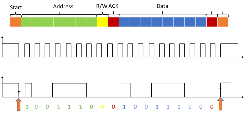
Start
At start, the data input is pulled low while the clock line is high. Then it is clear the communication begins.
In the following everything happens as already explained.
Address
The 7-bit address comes, as shown here, in the classic way 1 is high and 0 is low. Then comes the read/write bit, 0 for write and 1 for read, in this example it is written, i.e. sent from the master to the slave.
Acknowledge bit
The next bit is the acknowledge bit, which must be low for confirmation.
Data package
After that comes the data package with a size of one byte, also in the classic way: 1 is high and 0 is low.
Acknowledge bit
The data packet is followed by an acknowledgment, the acknowledge bit.
Stop
At the end comes the stop condition, the data line goes high while the clock line is also high.
Advantages of I2C
I2C has several advantages over other communication protocols, such as SPI and UART:
- Simple wiring: I2C requires only two wires (SDA for data and SCL for clock) to communicate with multiple devices, making it easy to connect to peripherals without requiring a large number of pins on the microcontroller.
- Multi-master support: I2C allows multiple master devices to share the same bus and communicate with different slave devices, enabling more complex systems.
- Addressable devices: I2C allows for up to 127 devices to be connected to the same bus, each with a unique address.
- Slow clock speed: I2C operates at relatively low clock speeds (up to 400 kHz), making it suitable for low-speed devices such as sensors and EEPROM.
Applications of I2C
I2C is widely used in various applications, including:
- Sensor networks: I2C is commonly used to connect sensors to microcontrollers, such as temperature sensors, pressure sensors, and accelerometers.
- Memory devices: I2C is used to connect memory devices such as EEPROM and RAM to microcontrollers.
- Display interfaces: I2C is used to communicate with display interfaces, such as LCD and OLED displays.
- Control systems: I2C is used in control systems for communication between microcontrollers and peripheral devices, such as motor controllers and LED drivers.
Conclusion
I2C is a widely used communication protocol that provides a simple and efficient way to connect microcontrollers and other digital circuits to peripheral devices. Its support for multi-master communication, addressable devices, and low clock speeds make it suitable for a wide range of applications, from sensor networks to control systems.
Read My Other Blogs:
Embedded C language Interview Questions.
Embedded System Interview Questions.
Automotive Interview Questions